
Audio Amplifier Wiring Diagram
Next we test first whether the converter is working or not, install the fuse on the secondary output. then input the black 12V supply for the red min for the + and this small cable for the brake or remote voltage, for testing it can be jumped directly with the + voltage.
Subwoofer C5198 A1941 Amplifier Circuit Diagram Diy 2000w High Power
Electro help: jbl bass 20 powered subwoofer - circuit diagram Subwoofer tl072 circuito circuitstoday wiring Subwoofer amplifier circuit 100w diagram output transistor audio diy board power.. 12v Car Subwoofer Circuit Diagram 19 Jul 2023.

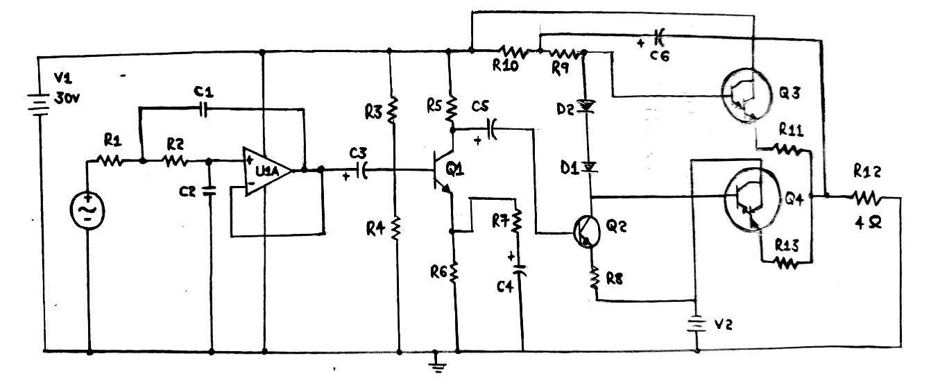
Subwoofer amplifier 100W output with Transistor Subwoofer amplifier
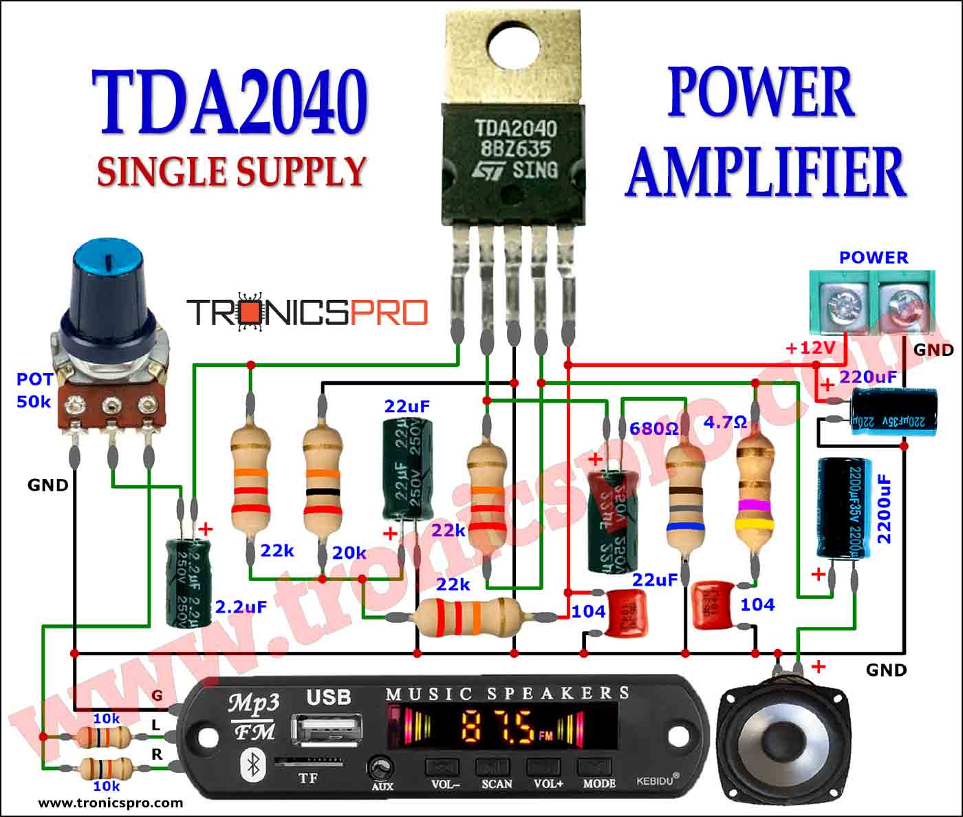
It is a power amplifier for the car radio, so uses voltage of power supply is 12 volts 14.4 volts. Importance, it is able to response frequency from 35 Hz to 15 KHz. We know the feature of TDA 2005 amplifier circuit diagram enough. We let to see how it works better. Recommended: 50W-75W integrated Amplifier

100 watts subwoofer amplifier circuit diagram Amplificador
Crossover for subwoofer circuit diagramSubwoofer booster circuit amplifier 12v pcb layout bass audio power diy electronics diagram schematic electronic ic car manual board projects Circuit amplifier subwoofer tda2030 diagram ic using 12v circuits schematic audio power wiring working guitar pcb car diagrams theater transistor5.1 subwoofer.
subwoofer power amplifier circuit
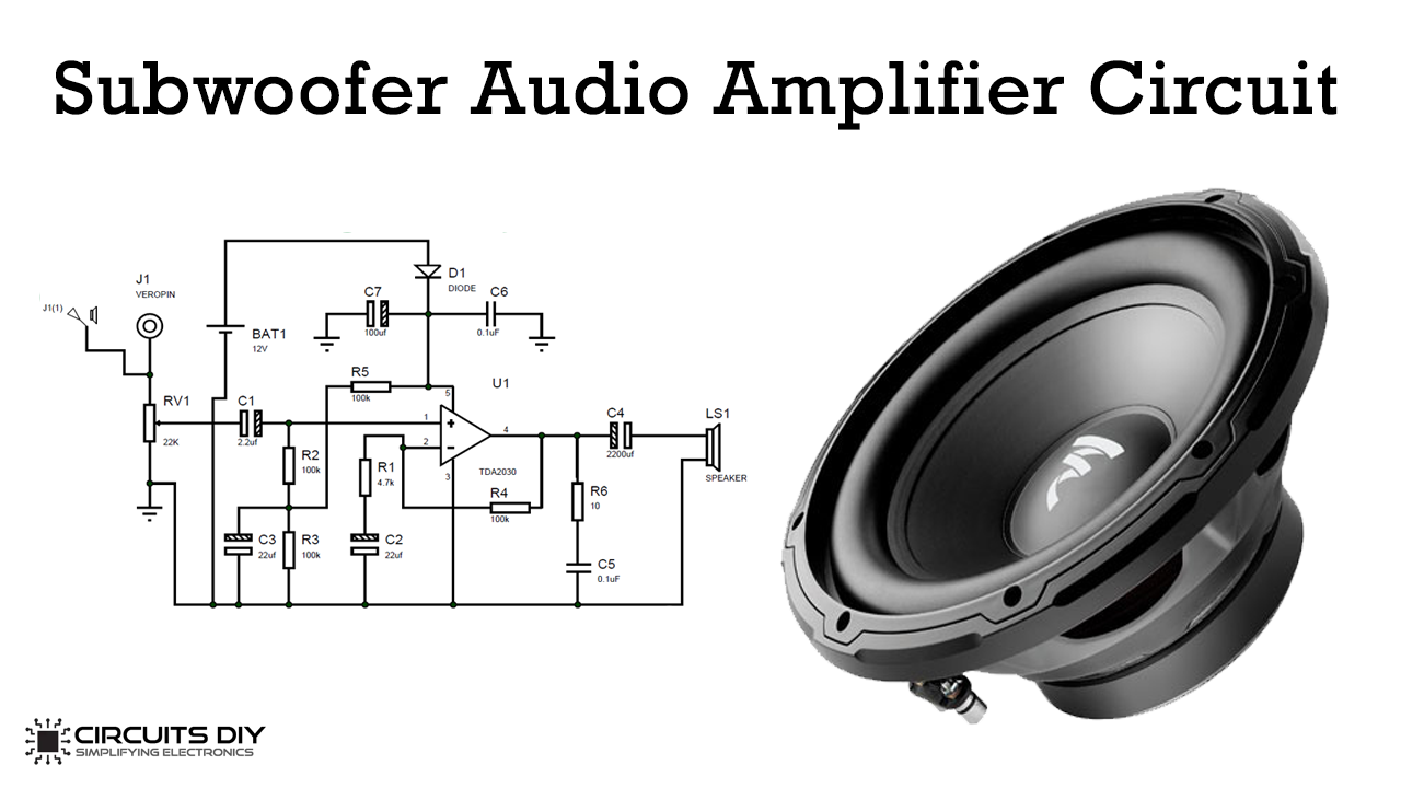
Step 1: Tda2030 TDA2030 amplifier circuit 12v, it is possible to operate the TDA2030 amplifier circuit in 12 volts, but we should follow the instruction to building properly functioned 12v TDA2030 amplifier Ask Question Step 2: Circuit Diagram and Working
Subwoofer Amplifier Circuit AllInclusive Way to Better Sound Quality
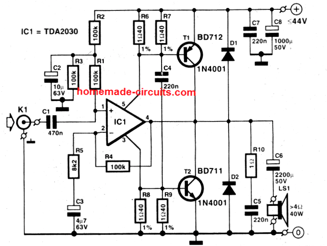
How it works In Figure 1 is shown the 50W BCL 12v car audio amplifiers circuit, at pin 9 and pin 10 of IC1 into the power supply from the battery 12 volts. Then pin 6, 12 and 17 are connected to a negative voltage, there are two capacitors C7, C8 serves as eliminating interference and power backup for IC1, respectively.

Buy Kl 180 1200W Car Subwoofer Amplifier Board Audio Power Module DIY
The car sector is one of the best places to use audio amplifiers. For example, the audio amplifier is used to amplify the audio signal in vehicles such as autos. So, in this Tutorial, we are going to make a "12V Car Audio amplifier circuit 50W-65W". The TDA1562Q integrated radio amplifier is used in the circuit.
Subwoofer Wiring Diagram 1 Channel Amp Collection
Choose from a vast selection of car audio, electronics and GPS tracking systems

Car Subwoofer Amplifier Circuit Diagram Pdf Home Wiring Diagram
Easy Order PCB Video assembling and test power amplifier subwoofer The circuit use TDA7388 as the power amplifier and it upgradeable to TDA7560. For the Active Lowpass filter, I use a NE5532 IC. I design this project

How To Connect A Car Amp To A Home Stereo (With Diagrams) Car audio
12V Car Subwoofer Circuit Diagram. Web 12v 200w subwoofer circuit diagram datasheet, cross reference, circuit and application notes in pdf format. It is a power amplifier for the car radio, so uses voltage of. Our subwoofer wiring calculator allows you to figure out how to wire your dual 1 ohm, dual 2 ohm, and dual 4. Subwoofer Amplifier.

Subwoofer Amplifier Circuit Diagram
The circuit diagram of this project is shown below. 100W Subwoofer Amplifier Circuit Diagram 35V power supply Circuit Diagram More Circuit Layouts LA4440 Amplifier, Tone Control & MP3 Bass Tone Control Circuit Diagram 2N3055 MJ2955 Class-AB Amplifier Circuit Diagram LA4440 Stereo Amplifier Circuit Diagram

DC 12V 24V Car Subwoofer Amplifier Board Audio Stereo Amplifier Board
Subwoofer amplifier circuit. This subwoofer amplifier circuit consists of a TL072 low-noise JFET dual operational amplifier (IC1) and two LM1875 (IC2 and IC3) power amplifiers. Circuit operation. In stereo mode, each half of the TL072 operates as a non-inverting input amplifier, with a gain of about 2.8 times as determined by feedback resistors.

12V Car Subwoofer Circuit Diagram
12V Car Audio amplifier circuit, 50W - 65W with PCB - ElecCircuit.com. Check Details. Pin on 400watt RMS. Check Details. Subwoofer Amplifier Circuit [Explained] with Application. Check Details. 12v Subwoofer Amplifier Circuit Manual - Circuit Diagram Images. Check Details. 200w Heavy Bass Mono Amplifier Circuit For Subwoofer | JLCPCB - YouTube.
12v Subwoofer Amplifier Circuit Manual
Cheap car subwoofer filter circuits. This car subwoofer circuit set Suitable for use with a great car audio system. Since this circuit is designed to operate with a 12 volt DC power. But if you put it to use with a home stereo, It does not have any rules. This subwoofer circuit set is designed to have a cut-off frequency of 200 Hz.

subwoofer circuit diagram Electronics Help Care Circuit diagram
Tda7294 100w audio amplifier todays circuits engineering projects 20w using tda7240 12v 600w mono car powerful bass subwoofer board player automotive module 150w power under repository 21189 next gr 44w stereo circuit tda1553 soldering mind schematic tda2040 integrated 5 best 40 watt explored homemade tip142 tip147 200w dc tl494 ei33 electronics tda1562 datasheet 70w high diagrams schematics.
150W Amplifier Circuit 2SC2922 2SA1216 Sanken TRONICSpro
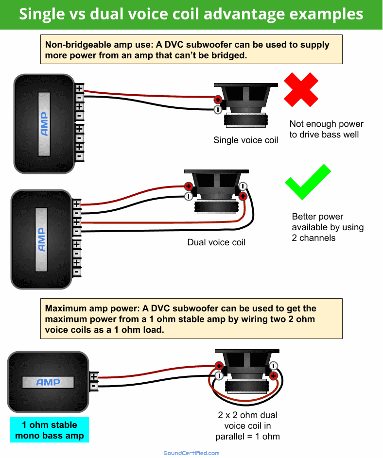
The diagrams are below, but first let's explain a few important terms. SVC A single voice coil sub with two wiring terminal posts, one marked positive and the other marked negative. DVC A dual voice coil sub with four wiring terminal posts, two positive terminals and two negative terminals.